The goal behind this short blog post is to give a broad overview of the Hoonipig aero development. Verus engineering was one part of this multiple company project, primarily dealing with creating the bodywork, ductwork, and aerodynamic performance necessary to tackle Pikes Peak. Scarbo Performance, BBi, and Verus Engineering kicked the project off in mid January of 2022, with merely an idea, a goal, and a lot of work ahead.
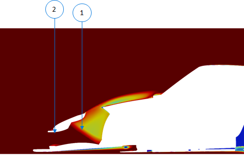
Front Aerodynamics
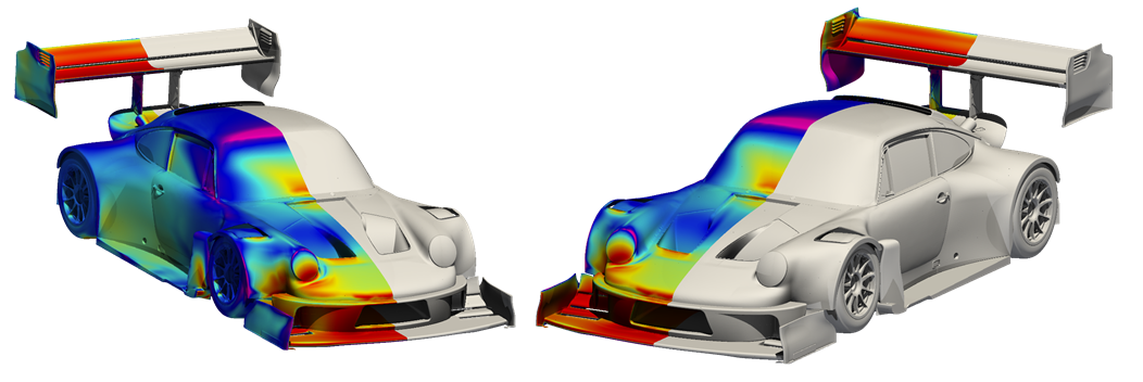
- The front splitter accounts for 35%-45% of the total vehicle's downforce
- The winglets are independently adjustable for aero balance and overall downforce targets
- The splitter package was specifically designed to keep balance consistent through a large range of ride heights.
- The splitter size was kept small to keep ride height sensitivity to a minimum.
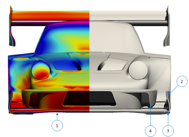
- The raised center section ensures adequate airflow to the floor, even under low ride heights and heavy braking (#1 in the above image).
- If the splitter touches the ground various design elements ensure adequate downforce is still produced. This keeps downforce consistent even in extreme conditions.
- The rear of the splitter endplate was developed to push airflow out and around the body and tires (#2 in the above image).
- The vortex generator seals the side of the splitter even at high ride heights (#3 in the above image).
- The bumper's turning vane controls air around the bumper and feeds the winglets better airflow (#4 in the above image).
Floor Aerodynamics
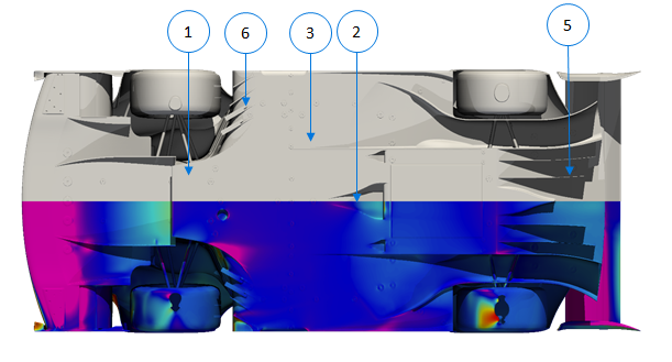
- The floor produces between 35% and 40% of the total vehicle downforce.
- Overall the floor features a mild design due to the high ride height window of the car's design concept.
- The mid splitter is fed from the front splitter (#1 in the above image).
- Three NACA ducts feed the engine, gearbox, and turbo manifolds cool ambient airflow (#2 in the above image).
- The outer tunnels start very early and help recover pressure behind the car, which results in reduced drag and increased downforce (#3 in the above image).
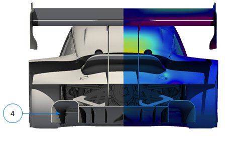
- The rear diffuser's design was specific to the high ride heights and to reduce ride height sensitivity, ensuring downforce production when attacking the mountain (#4 in the below image).
- The strakes control airflow within the diffuser to improve performance (#5 in the above image).
- Vortex generators behind the front wheels utilize dirty air to re-energize the flow on the underside of the body (#6 in the above image).
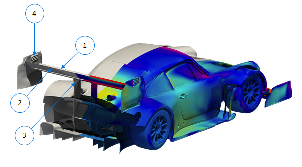
Rear Wing Aerodynamics
 The rear wing is the Verus Engineering, off-the-shelf, V2X wing profile which features a 300mm main element (#1 in the image below) and a 200mm second element (#2 in the image below) to produce high levels of rear-end downforce.
- A bottom-mounted wing was a design decision based on aesthetics and location for proper aero balance (#3 in the image below).
- The endplates control airflow from around the body to improve rear wing performance. The vents (#4 in the image below) decrease the endplate vortex and decrease drag. The vent is 3D printed and bonded to the carbon endplate.
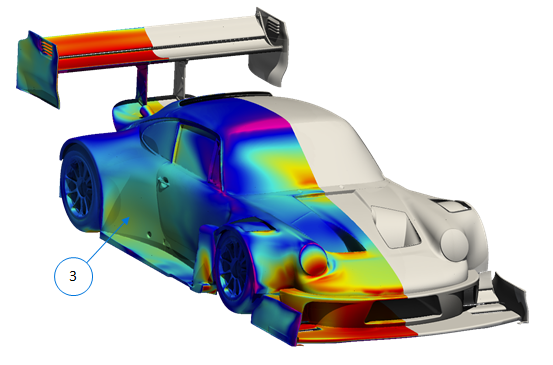
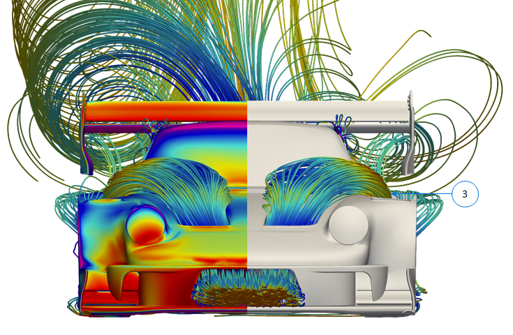
Bargeboard Aerodynamics
 The bargeboard (#1 in the above image) is a complex airflow conditioner that fixes the fact the car is substantially wider than a factory car. This creates aerodynamic issues which this unit corrects.
- The bargeboard cleans up the dirty flow and pushes the airflow outboard (#2 in the above image).
- The help airflow around the rear quarter panels (#3 in the below image) and improve overall efficiency of the vehicle.
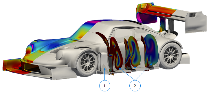
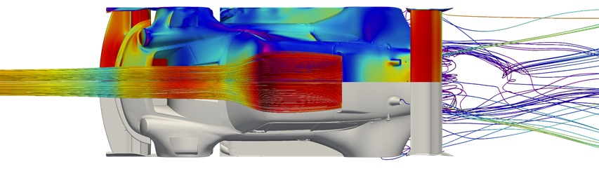
Radiator Ducting
 The radiator ducting was optimized for maximum performance of the radiator (#1 in the above image) which is supplier by PWR North America.
- The radiator flow was simulated in CFD based on PWR supplied airside pressure data.
- Both the inlet (#2 in the above image) and outlet ducting (#3 in the below image) are critical for cooling and aero performance.
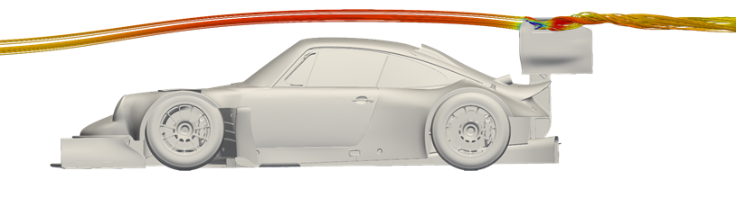
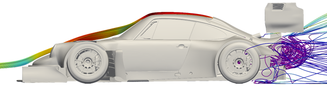
Intercooler Ducting
- Proper airflow to the intercooler is important to maximize performance.
- The shallow duct on top of the deck lid has no effect on the rest of the flow rearward. This is benefiial for aero performance.
- The outlet of the intercooler dumps into the engine bay and is evacuated out of the opening in the rear of the car, butween the body work and the floor.
Conclusion
This is a very broad overview of the aerodynamic development on the Hoonipig. A few hundred iterations in CFD were tested to get to this point. The bespoke aero kit is one of the neatest projects we have been a part of to date.