Purpose:
This document contains diagrams, information, and notes regarding the CFD analysis of the rear diffuser modular kit for the FT-86 SpeedFactory rear diffuser.
Design:
The rear diffuser was designed for those who want an extremely functional piece that dramatically reduces drag and increases downforce. We believe this to be the highest downforce producing unit on the market at this time. The aesthetic goal was to blend into the vehicle's exterior and integrate it as if an aggressive OEM piece. It was designed to work very well with the race front splitter with a 49/51 aerodynamic split. The final goal was to create a kit that allows the user to thoroughly cover up the suspension components direction in-front of the rear diffuser. This further improves the rear diffuser’s performance.
The design was optimized through CFD analysis. Each analysis was done using a half-car analysis since no yaw testing was completed. This is done using symmetry down the centerline of the car. Significantly less computational processing power is necessary when using a half-car model and was the reason behind this analysis approach. The meshing of the car is done using first a surface mesh and then volume mesh. To find a suitable mesh size for the analysis, a grid convergence study was done. A volume mesh count of 10 million cells was considered within the room
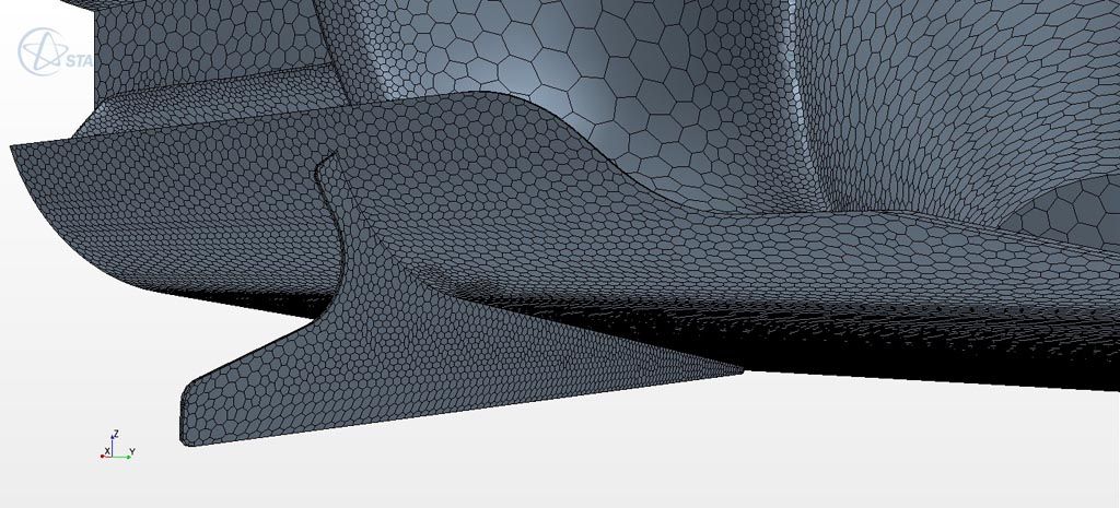
Surface Mesh on Rear Diffuser
The CFD post-processing offers both visualizations of the flow and numerical data. Using both of these we can make educated guesses as to the changes to make to optimize parts of the system to reach design goals. Pressure plots allow us to visualize the location of high and low pressure very easily.
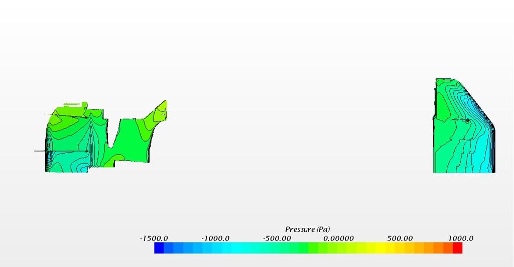
Both Rear Diffuser and Splitter Pressure Plot Shown Off Car (bottom view)
Vector and pressure plots allow us to see how the
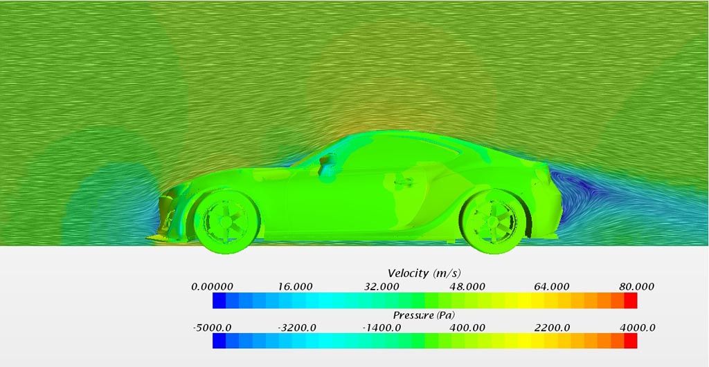
Vector Plane Plot
Streamlines are another powerful tool to find how and where we can make improvements to the design.
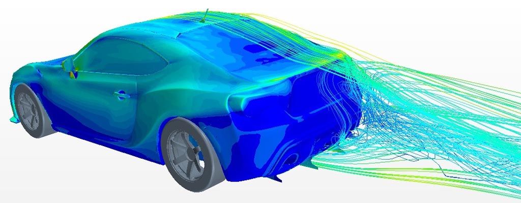
Wall Shear Stress on the body and Streamlines as Air Velocity
A new post-processing technique in our arsenal is arrows. We can now visualize where the air is being directed via CFD analysis.
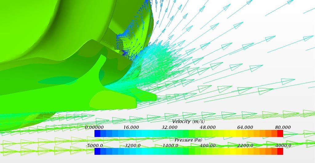
Arrows as Air Velocity, Body as Pressure Plot
Data:
The rear diffuser increases downforce and dramatically improves aerodynamic balance. While numerically the CFD analysis shows we actually increased drag, we believe this to be inaccuracy and a result of our car model not being accurate in the suspension/diff area. In real-world

Numerical Data
Conclusion:
Real-world benefits may differ as this is computational analysis. Something as simple as ride height or wheel choice can vary results, as well as various other aspects. Real-world results could be better or worse than what is shown above. We must remember though, given the model we started with, the above data is accurate and should translate to a real-world benefit.
Very few companies perform CFD or wind tunnel analysis on any of their aerodynamic pieces. As a consumer, you can rest assured that you are receiving a quality component with an engineering analysis that has proven to benefit the vehicle's characteristics.
FT-86 Modular Rear Diffuser Information