Purpose:
This document contains diagrams, graphs, and notes regarding the CFD analysis of the genuine FT-86 SpeedFactory Street Front Splitter.
Design:
The splitter went through many design iterations before the shape was finalized. Each analysis was done using a half-car analysis since no yaw testing was completed. This is done using symmetry down the centerline of the car. Significantly less computational processing power is necessary when using a half-car model and was the reason behind this design approach.
The meshing of the car is done using first a surface mesh and then volume mesh. To find a suitable mesh size for the analysis, a grid convergence study was done. A volume mesh count of 10 million cells was considered within the room of accuracy with the turbulence model.

Figure 1: Surface Mesh
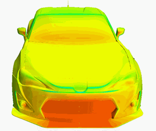
The CFD post-processing allows the visualization of the flow. With this visualization, changes can be made to optimize parts in a system. The pressure plots allow locations of high and low pressure to be visualized easily.

Figure 2: Pressure Plot
Vector plots allow the visualization of how the flow is moving along a plane. Looking at Figure 3, the formation of vorticity on the splitter can be seen, a positive phenomenon which we were seeking while designing the splitter.

Figure 3: Vector Plot
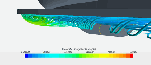
Streamlines are another powerful tool to locate vortices. Vorticity control is necessary to keep the aerodynamics working on the rest of the car and helps create downforce. Figure 4 shows the vorticity forming off the front of the splitter which is also shown in Figure 3.

Figure 4: Streamline Showing Vorticity
Data:
The street splitter makes downforce, reduces drag, and improves aerodynamic balance. The values can be seen in the table below.

Conclusion:
Real-world benefits may differ as this is computational analysis. The car model is accurate as are all the inputs for this analysis. However, there are minute details that are not included or accounted for. To name a few, the underbody is not completely accurate with the real world model, too many intricacies that with a CAD model are near impossible to account for. In addition, the rims will vary the aerodynamics of the entire car and could skew results. Something as simple as ride height can drastically vary results, as well as various other aspects. Real-world results could be better or worse then what is shown above. We must remember though, given the model we started with, the above data is accurate and should translate to a real-world benefit.
Very few companies perform CFD or wind tunnel analysis on any of their aerodynamic pieces. As a consumer, you can rest assured that you are receiving a quality component with an engineering analysis that has proven to benefit the vehicle's characteristics.
Street Front Splitter